


 0
0
 0
0
Your basket is empty...
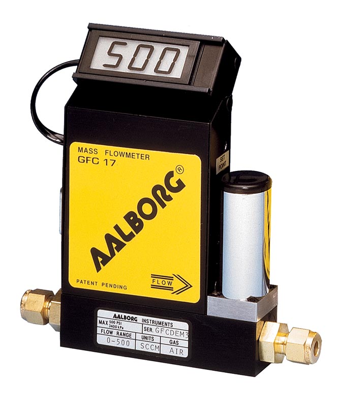
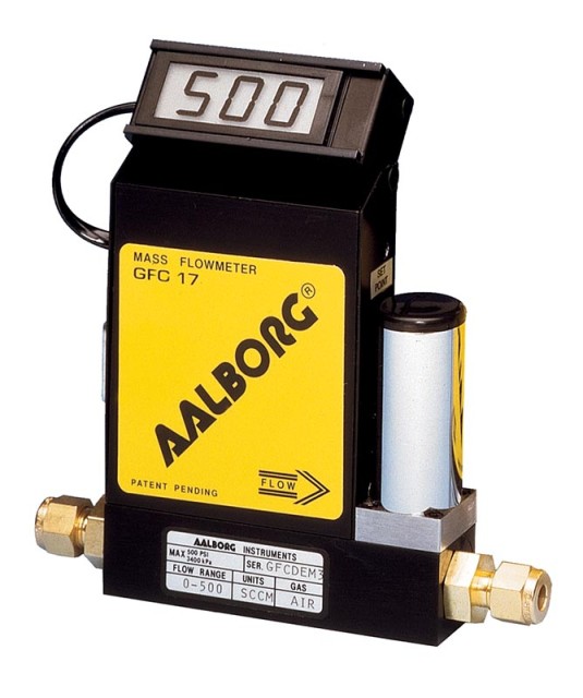
SS Mass Flow Controler, model GFC17S (max.flowrate 10l/min air)
Reference: GFC17S-ABCD-EF-PLYN-PRUTOK
Mass flow controller Compact, self-contained GFC mass flow controllers are designed to indicate and control flow rates of gases. The rugged design coupled with instrumentation grade accuracy provides versatile and economical means of flow control. Design features Rigid metallic construction.
Your price
on inquiry
Availability: ask us
Product description
Product description
Mass flow controller
Compact, self-contained GFC mass flow controllers are designed to indicate and control flow rates of gases. The rugged design coupled with instrumentation grade accuracy provides versatile and economical means of flow control.
Design features
- Rigid metallic construction.
- Maximum pressure of 1000 psig (70 bars).
- Leak integrity 1 × 10⁻⁹ smL/sec of helium.
- NIST traceable certification.
- Built-in tiltable LCD readout.
- Local or remote setpoint control.
- 0–5 Vdc and 4–20 mA signals.
- Circuit protection.
- TIO Totalizer option.
**CATALOG NUMBER OF MASS FLOW CONTROLLER IS COMPOSED ACCORDING TO YOUR PARAMETERS. ** What the letters ABCDEF means you can see in technical parameters. Contact us, we will be happy to send you a quote.
Parameters
Parameters
| Brand: | GFC |
| Category: | Measurement and control / Gas measurement / Flow controllers |
Technical parameters
| Accuracy | GFC 17, 37 a 47: ± 1,0% FS. |
| GFC 57, 67 a 77 (flow range 20–100%): ± 1,5%; optional enhanced accuracy ± 1,0% FS | |
| GFC 57, 67 a 77 (flow range 0–20%): ± 3%; optional enhanced accuracy ± 1,0% FS | |
| CALIBRATIONS | Performed at standard conditions [14.7 psia (101.4 kPa) and 70 °F (21.1°C)] unless otherwise requested. |
| REPEATABILITY | ±0.25% of full scale. |
| RESPONSE TIME | Generally 2 seconds to within ±2% of actual flow rate over 25 to 100% of full scale. |
| TEMPERATURE COEFFICIENT | 0.15% of full scale / FC. |
| PRESSURE COEFFICIENT | 0.01% of full scale / psi (0.07 bar). |
| OPTIMUM GAS PRESSURE | 25 psig (1.73 bars). |
| MAX. GAS PRESSURE | 1000 psig (70 bars) maximum GFC 17, 37, 47. 500 psig (34.5 bars) GFC 57, 67, 77. |
| TURN DOWN RATIO | 40:1. |
| MAX. DIFF. PRESSURE | 50 psi for GFC 17/37/57/67 and 77 (3.4 bars), 40 psi for 47 (2.7 bars). |
| GAS and AMBIENT TEMP | 32 °F to 122 °F (0 °C to 50 °C). 14 °F to 122 °F (-10 °C to 50 °C) – Dry gases only. |
| MATERIALS FLUID CONTACT | a. Aluminum models GFC Series: anodized aluminum, 316 stainless steel, brass and Viton O-rings. |
| b. Stainless steel models GFC17S, 37S, 47S, 57S, 67S and 77S: 316 stainless steel and Viton O-rings. | |
| Optional O-rings: Buna , EPR and Kalrez . | |
| ATTITUDE SENSITIVITY | No greater than +15 degree rotation from horizontal to vertical; standard calibration is in horizontal position. |
| OUTPUT SIGNALS | Linear 0–5 Vdc. (1000 ohms min. load impedance); 4–20 mA (0–500 ohms loop resistance) Max noise ±20mV. |
| COMMAND SIGNALS | Analog 0–5 Vdc or 4–20 mA for remote set point mode; NPN compatible purge /valve off. |
| CONNECTIONS | GFC 17: 1/4" compression fittings. Optional: 6mm, 3/8" and 1/8" compression fittings or 1/4" VCR. |
| GFC 37: 1/4" compression fittings. Optional: 6mm and 3/8" compression fittings or 1/4" VCR. | |
| GFC 47: 3/8" compression fittings. | |
| GFC 57: 3/8" compression fittings. | |
| GFC 67: 1/2" compression fittings. | |
| GFC 77: 3/4" FNPT fittings. Optional: 3/4" compression fittings. | |
| LEAK INTEGRITY | 1 × 10⁻⁹ smL/sec of helium maximum to the outside environment. |
| TRANSDUCER INPUT POWER | GFC 17, 37 and 47: Universal +12 Vdc to 26 Vdc, 200 mA maximum. |
| GFC 57, 67 and 77: +12 Vdc, 800 mA; +24 Vdc, 650 mA optional. | |
| CIRCUIT PROTECTION | Circuit boards have built-in polarity reversal protection. Resettable fuses provide power input protection. |
| DISPLAY | 3–1/2 digit LCD, 0.5" high characters. |
| CE COMPLIANT | EN 55011 class 1, class B; EN50082–1. |
Explanation of the device code
GFC17A-ABCD-EF-GAS-FLOW
- A = type of seal
- B = fitting size (connection)
- C = display (L = including display, N = no display)
- D = power supply (2 = 12VDC, 4 = 24VDC for GFC 57, 67 and 77, 6 = 12 to 26 VDC for GFC 17, 47 and 47)
- E = output (A = 0 to 5 VDC, B = 4 to 20 mA – local, C = 0 to 5 VDC / 0 to 5 VDC, D = 0 to 5 VDC / 4 to 20 mA, E = 4 to 20 mA / 4 up to 20mA, F = 4 to 20mA / 0 to 5 VDC)
- F = digital output (always = 0)
Use
| Medium | Plyn |
| Max. flowrate | 10l/min |
Operating conditions
| Analogue output | na výběr |
- Show all
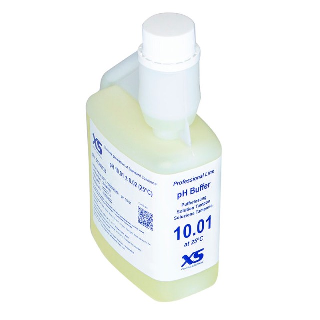
XS Buffer Solution pH 10,01 ± 0,02 / 25°C yellow with DAKKS certificate, 1x500 ml
![]() In stock 2 kson inquiry
In stock 2 kson inquiry
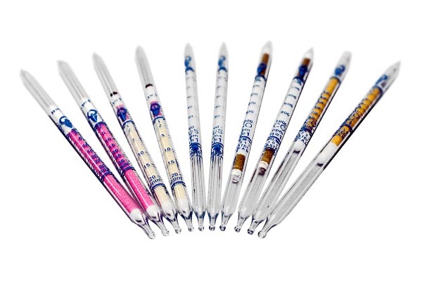
Carbon monoxide - detection tubes (dosi) 1.04-2000ppm, package 10 pcs
![]() Availability: ask uson inquiry
Availability: ask uson inquiry